What is a Differential and what does it do?
I’ve always called the whole rear axle the differential? So which part of the rear end assembly is the differential?
The differential is contained within the central axle housing. This is the central part of the rear axle also known as the differential carrier. It is easily recognizable as the drive shaft attaches directly to it.
The differential has three main functions:
The first function is as we said above, to redirect drive power to the rear wheels. This occurs while the vehicle is moving straight ahead and while making a turn. The drive is directed from the drive shaft to the axle shafts. This is accomplished by the ring and pinion gears explained below. We will describe this process later in the article.
The second function is to use gear reduction to multiply engine power applied to the wheels. This occurs to optimize acceleration. If there was no gear reduction, the engine may not be able to get the vehicle moving. If it did manage to begin accelerating, it would make the vehicle difficult to drive. To accomplish this, the ring and pinion gearing reduces the speed at the output by a ratio of anything from 2:1 to 5:1. The ratio is dependent on the engine size, vehicle type and vehicle purpose.
The third function is to help the vehicle to make turns efficiently. If the differential did not make allowances for different rotational speeds for the outer and inner wheels, at least one tire would lose traction with the ground. While going around corners, this would result in what is called ‘wheel hop’. This impedes the vehicle handling and smooth turning ability.
Expanded benefit of a differential:
An addition to the third point should also be mentioned here. Although a less common system, due to their complexity, limited-slip differentials are being equipped to more and more vehicles. They have a variety of brand names including positraction (GM), Sure-Grip (Mopar), Anti-Spin (Dodge), traction-Lok (Ford) and others. Where the basic system applies power to one wheel, the limited slip differentials apply power to both wheels under normal driving conditions. This is adjusted when turning or in situations of low traction where power is applied to the wheel having the most traction. In low traction environments such as wet roads, snow, mud, sand etc. the selective application of power to the wheel with more traction can be a huge benefit to avoid getting your vehicle stuck (in the case of mud sand of snow) or sliding (in the case of wet/snow). Due to the complicated nature of their operation, we will discuss limited-slip differentials as an individual topic later.
Why is the differential needed to apply different rotational speeds for turning?
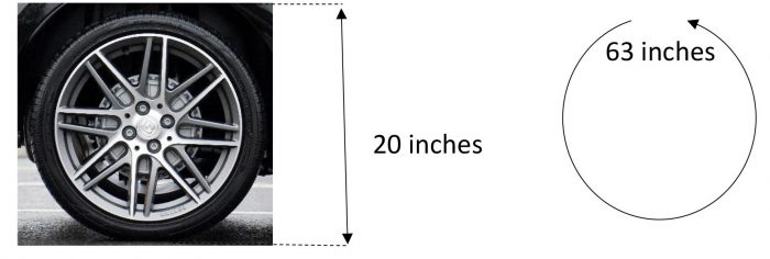
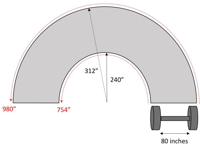
This is best explained with an example, see the illustration below. Let’s take a 16 inch wheel/rim and a tire that adds 2 inches to the top and bottom of the wheel. This makes an overall diameter of 20 inches from the top surface of the tire to the bottom. For every single rotation of this wheel, the distance travelled is about 63 inches. If you take two wheels and place them 6 feet or 80 inches apart (like the width of a car). If you make them go around a 180 degree corner (of inside radius 20 feet/240 inches), the wheel closer to the inside of the corner travels a lesser distance than the wheel closer to the outside of the corner. This means the inside tire needs to rotate a lesser amount of times (12 times in our example) than the outside tire (15.5 times).
So the amount of rotational drive applied to either wheel can be ‘different’. This is the origin of the name differential. It simply describes a function of differentially applying drive to wheels depending on their needs.
So how is this accomplished? Well, let’s begin with the question, how is the drive power from the drive shaft transferred to the wheels?
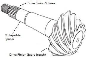
The U-joint of the drive shaft connects to the differential pinion yoke. Rotational force is applied from the yoke to the splines on one end of the pinion gear. On the other end of the pinion gear are hypoidal gears (spiral beveled helical teeth). See the image below as an illustration. As the pinion rotates, the teeth mesh with teeth in the ring gear and this is the point where rotational power is redirected 90 degrees towards the wheels. The engine power is multiplied based on the rear axle ratio.
Rear axle ratio? I’ve heard of that but what is it?
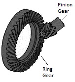
This is the ratio of teeth on the pinion gear and the ring gear. The ring ger is illustrated with the pinion gear below. There is always more teeth on the ring gear. For example, if the pinion gear has 10 teeth and the ring gear has 40 then the rear axle end ratio is 4:1. This means for every 4 turns of the pinion, the ring gear will only rotate once. Gear ratios vary depending on the vehicle. This will also depend on the gearbox of the vehicle as it has gear ratios also. Changing the rear axle ratio can change the behavior of the vehicle such as more low RPM power for towing or another ratio for higher top speed.
So do the pinion and ring gear fail and need replaced?
Yes they do. The pinion and ring gear are sometimes collectively called the differential drive gears. Despite being made of hardened steel, all the torque applied to the pinion gear is applied through the pinion gear (teeth) to the ring gear. The area of the meshed teeth on the gears is a relatively small area to endure large forces. Over time and use mechanical wear will damage these gears. Additionally, the bearings holding these pieces in place also wear as they rotate and frequently need replacing.
How do you fix ring and pinion gear failures?
At Houston Rebuilt Axles, we perform this operation frequently. Failure of these components requires their replacement. However, it is not a simple remove and replace. For example, the pinion gear is supported front and back by two tapered roller bearings. The rear pinion bearing (the gear side) needs to be pressed onto the pinion gear shaft using a hydraulic press to the correct position. The front or U-joint side bearing is a slip on. Between the bearings are pinion preload shims. These are solid or collapsible spacer (also known as a crush sleeve), used to put mild pressure on the front and rear bearing to facilitate setting the bearing preload.
What is the bearing preload on a pinion gear?
The bearing preload is a load applied to the two bearings holding the pinion in place. This is a value set by the manufacturer and, in collaboration with the crush sleeves, spacers (or preload shims) and pinion gear nut, must be set correctly to prevent excessive movement of the pinion gear. Improper placement of the pinion gear will result in the contact area (tooth depth) of the gears on both the pinion and the ring gear to be offset. This will improperly distribute drive force to the gears. Even the pinion shim thickness must be checked to make sure the gears are placed exactly in the correct position. Improper fitment can result in noisy gears and premature failure of the components. It is the fine details such as these that make it so important to have our professionals at Houston Rebuilt Axles repair your differential!
What about the ring gear?
As the pinion placement is so important, it’s no surprise that the ring gear is just as important as the two must mesh their gears/teeth exactly. The ring gear is not surprisingly a ring of hardened steel with the same hypoidal/spiral helical teeth on only one side of it. The helical teeth perfectly matched to those on the pinion gear. This side is referred to as the convex side or drive side. The other side of the ring does not have any teeth and is called the concave or coast side. While we are on terminology, the inner side of the teeth on the gear is referred to as the toe and the outside part of the teeth is referred to as the heel. These terms are used when evaluating pinion to ring gear alignment/engagement to ensure perfect placement.
What is backlash?
Another factor in evaluating gear placement is the ‘backlash’ which is the amount of movement in the ring gear when the pinion gear is held stationary. The movement is due only to the gap left between the teeth when meshed together and again, must be within manufacturer’s specifications.
What is the ring gear attached to and how?
The ring gear is bolted directly to the differential case by bolts through the case into threaded holes in the back or coast side of the ring gear. This is how drive is transferred directly to the differential case and thus to the half shafts.
So from this point we can see how drive power is transferred from the drive shaft to the differential gearing. In the next article, we will discuss how it is delivered ‘differentially’ to the wheels through the axle shafts.