So now that the differential has drive power applied to it
How does it apply that power differentially to the wheels?
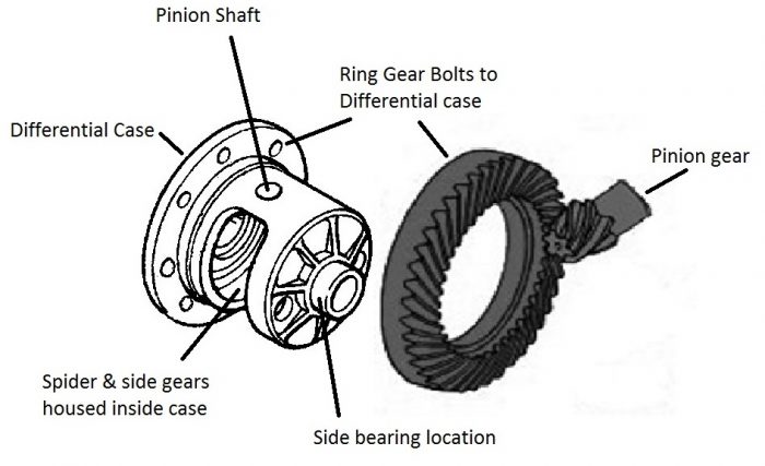
Front and rear differential explained, this article will help explain standard and single-pull differentials. First off, let’s discuss what makes up the components of standard differentials or single-pull differentials. Limited-slip differentials, torque-vectoring differentials and other differentials will be talked about in a different article. As previously mentioned, the ring gear is attached to the differential case. It is usually made of cast iron but sometimes aluminum. The differential case is illustrated below.
Spider Gears
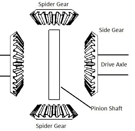
Inside the differential case are the spider gears (also referred to as pinion gears) and side gears. The term spider gears allows dissociation of them from the pinion gear driving the ring gear. To keep this dissociation, we will use spider gear in this article. The spider gears are hardened steel beveled gears. The pinion shaft extends through them from one end of the differential case to the other. As the gears are beveled, the wider part of the gear faces the differential casing. The narrower part of the bevel faces the center/opposite gear. See the illustration below. In heavy duty applications, there can be four spider gears and two pinion shafts. This is for added durability and higher power transfer. In this case, one pinion shaft has a hole that the other one sits within as they cross paths.
Side Gears
On either side of the spider gears are side gears which mesh with the spider gears. These are also hardened steel beveled gears. In their case, the wider end of the bevel faces the axle shafts extending to the wheels. The narrower sides of the bevels faces each other and the spider gears. See the illustrations below of the differential gears separately and while housed in the differential case.
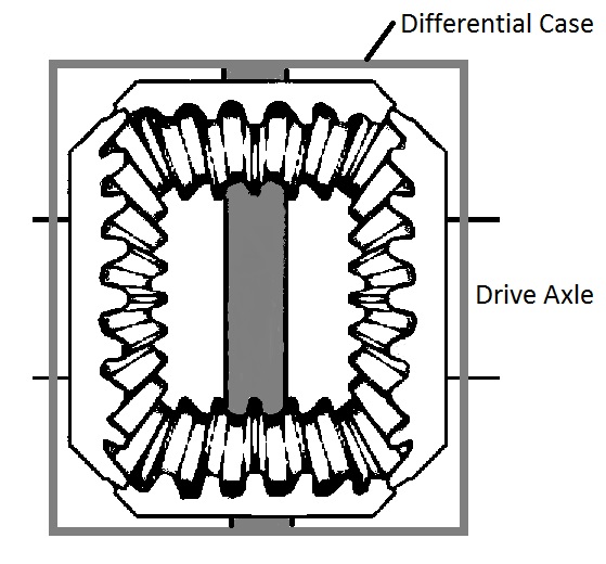
As the ring gear is attached to the differential case, the case turns as the ring gear does. When the case turns, the power flow is through the case into the spider gears (via the pinion shaft) and on into the side gears. As the side gears are attached by splines to the axle shafts, they transfer the drive to the wheels. Some differential side gears have c-locks to hold the axles in place. Rotational force in beveled gearing cause them to push away from each other against the differential case. There are thrust washers placed between the case and each gear to provide a low friction surface and reduce wear on the components
So how do the standard differentials gears allow wheels to turn at different rates?
While driving straight, both wheels turn at the same rate. In this instance, the differential case rotates turning both axles at the same rate. The spider and side gearing do not have any contribution to the drive at this point. They simply rotate within the case but don’t rotate in relation to each other. This is comparable to a situation where the spider and side gears are bonded to each other. They are not able to rotate but only rotate along with the casing.
Like in our previous turning illustration, let us now take a left turn as an example. Once a left turn occurs, the outer wheel (right wheel in this case) will turn more than the inner (left) wheel. The wheels are connected to the side gears via the axle shafts. The side gears related to each wheel will thus turn at this rate i.e. right side gear will turn more than the left side gear. The right side gear turning at a faster rate will cause the spider gears to begin to rotate around the left side gear. The rotation of the spider gear around the left side gear will accommodate the extra rotation required by the outer wheel (right).
In our example, the right side gear will be turning faster than the differential case. The left side gear will be turning slower than the differential case. The case rotates at a speed that is the average of the two side gears. Decreasing the turning radius of the bend (sharper turn), will result in the spider gears turning more around the side gears. This will account for the added difference in rotation of the inner and outer wheels.
Yes I see how the power is distributed to each wheel accommodating for different turning rates.
Great, however, there is a downside to this form of differential. This is a simple type of differential and in some situations, it can actually be troublesome.
What kind of problems can the standard differential cause you?
The differential just explained (standard or single pull) works by adding power to the wheel with least traction. As an example, if one wheel is on a surface with high traction such as pavement and the other wheel is on a surface with low traction such as mud, power from the rotating differential case will be applied to the wheel of least resistance i.e. mud. This is due to the engagement of the spider gears which will rotate around the side gear of the wheel on the higher traction surface. This will mean the wheel in the mud will spin and with little traction may result in the vehicle not being able to move off the surface.
That sounds like a big problem! Can it be overcome?
This problem has been overcome and how it is overcome depends specifically on which type of differential your vehicle is equipped with. Many vehicles now have locking differentials.
What is a locking differential?
A locking differential is one which applies some drive power to both wheels but still accommodates for extra rotation in one wheel while turning. There are several types of locking differentials and how they function varies with their application and manufacturer. In some cases, standard differentials can be converter to locking differentials. Houston Rebuilt Axles are experts and can advise you on what type of differential is best and most cost effective for your vehicle. We can also help you troubleshoot axle problems.
Types of locking differentials will be the topic of our next article